air brake foot valve diagram
POWER BOOSTER, Remote, HOW IT WORKS. 10 Pictures about POWER BOOSTER, Remote, HOW IT WORKS : Figure 9C-3. Treadle Valve (38Z225), Volvo Brake Valve BW-286171N and also [HG_5324] Air Brake Circuit Diagram Bendix Free Diagram.
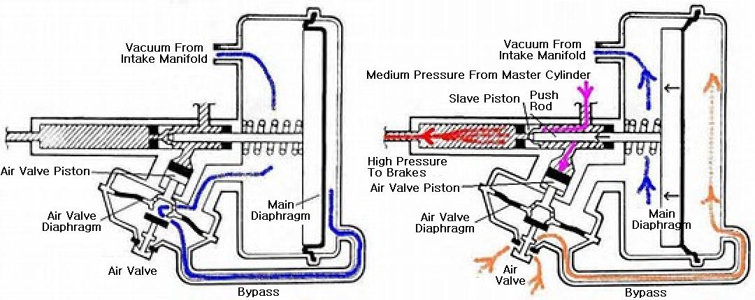
POWER BOOSTER, Remote, HOW IT WORKS
 www.mgaguru.com
booster brake remote brakes works hydraulic power pressure pedal diagram air cylinder control master valve function force which foot modulating
[HG_5324] Air Brake Circuit Diagram Bendix Free Diagram
![[HG_5324] Air Brake Circuit Diagram Bendix Free Diagram](https://static-resources.imageservice.cloud/10449920/air-brake-system-troubleshooting.png) xortanet.eatte.mohammedshrine.org
xortanet.eatte.mohammedshrine.org
bendix
[XL_9085] Air Brake Circuit Diagram Bendix Schematic Wiring
![[XL_9085] Air Brake Circuit Diagram Bendix Schematic Wiring](https://static-cdn.imageservice.cloud/3023050/wabco-abs-wiring-diagram-wiring-diagram-gp.png) xortanet.eatte.mohammedshrine.org
xortanet.eatte.mohammedshrine.org
wiring abs wabco bendix tabs brakes schematics 2s imageservice scientific cougar braking
[NF_3140] Air Brake Circuit Diagram Bendix Schematic Wiring
![[NF_3140] Air Brake Circuit Diagram Bendix Schematic Wiring](https://static-cdn.imageservice.cloud/730646/piping-diagrams-spring-brake-control-for-trailers-st-louis-truck.jpg) hisre.odga.mohammedshrine.org
hisre.odga.mohammedshrine.org
brake spring air control diagram bendix piping trailer truck diagrams trailers plumbing schematic suspension circuit valve sr reservoir louis st
[NF_3140] Air Brake Circuit Diagram Bendix Schematic Wiring
![[NF_3140] Air Brake Circuit Diagram Bendix Schematic Wiring](https://static-cdn.imageservice.cloud/133525/wabco-trailer-abs-wiring-diagram-wiring-diagram-database.jpg) hisre.odga.mohammedshrine.org
hisre.odga.mohammedshrine.org
abs wabco diagram wiring trailer bendix meritor brake schematic air 2m 2s electric circuit database configuration
Truck Crash Blotter: Truck Crash: Foundation Air Brake Fade; Scott L Turner
 truckcrashblotter.blogspot.com
brake air truck parts brakes components diagram pneumatic trucks hydraulic braking 2008 fade system howstuffworks bus systems buses disc works
Volvo Brake Valve BW-286171N
 www.premiumtruckpartsusa.com
brake valve bw bendix volvo premiumtruckpartsusa
Brakes & Air System | Page 2 | Couch Off-Road Engineering
 www.couchoffroad.com
brake valve exhaust foot air brakes system unimog parts
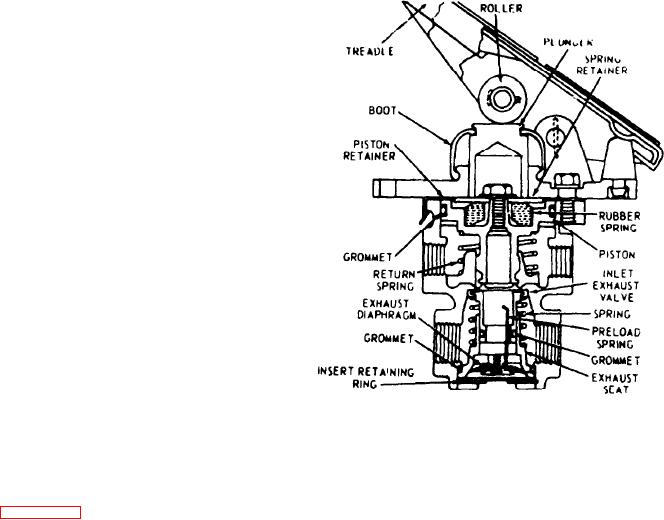
Figure 9C-3. Treadle Valve (38Z225)
 constructioncranes.tpub.com
valve treadle air components system 14p tm
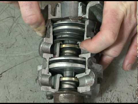
TREADLE VALVE.dv - YouTube
 www.youtube.com
valve foot bendix diagram treadle tractor trailer protection brake air control parts
Valve foot bendix diagram treadle tractor trailer protection brake air control parts. [nf_3140] air brake circuit diagram bendix schematic wiring. Booster brake remote brakes works hydraulic power pressure pedal diagram air cylinder control master valve function force which foot modulating